<--Previous Up Next-->
Grafting the fanfare wiring
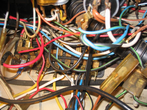
I added two splitters to the fuse box. The one on the upper left -- second terminal from the end -- is picking off *before* the fuse box fuse. This will supply the actual power to the fanfare horns, and I'll be adding my own in-line fuse. The second splitter is on the far right, downstream of the fusebox, where the black/yellow stock horn + wire attaches. This will supply activation power to the relay. To the right of the picture, running diagonally up and to the right, you can see the stock horn grounding wire (brown) that runs from the horn button to the stock horn. Well, what you mostely see is the long, clear plastic connector that protects the spade connector junction. It's disonnected in this picture. The two ends of the "break" are just in front of the black air hose. These leads will be routed through the horn selection switch.